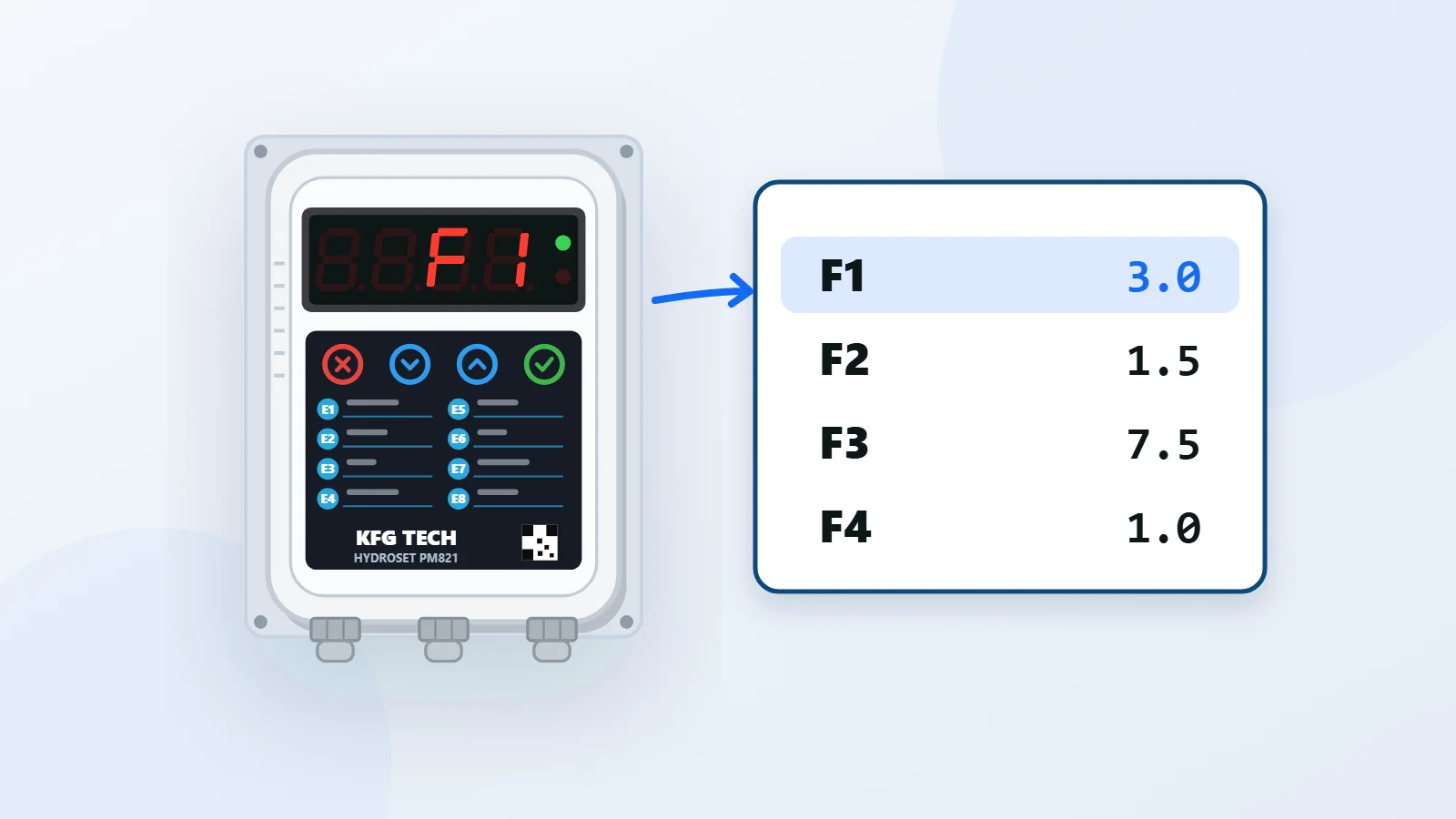
Setting a water pump controller in three steps: stop and start pressure (F1 and F2), the current limit (F3) and dry-run sensitivity (F4). With the pressure formula for any height and the factory values.
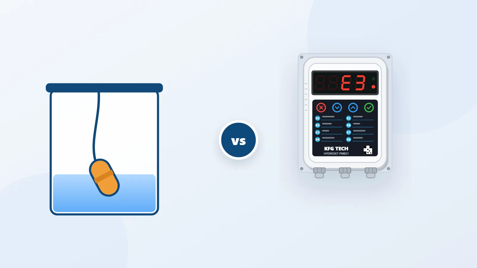
Pump controllers come in two types. In the mechanical type, pressure is set with a screw and a spring and has no exact number. In the digital type, such as HYDROSET PM821, every setting is a number you see on the display. This guide explains how to set up the digital type step by step, and ends with a note on screw-adjusted models.
Know these before you start
- Building height: from where the pump is installed to the highest tap, in metres.
- Pump current: the amp figure on the pump nameplate.
- Pressure vessel: whether you have one or not.
Entering the settings
On HYDROSET you enter the settings with the Confirm key and change the parameter and its value with the Up and Down keys. You leave the settings with the Cancel key. You can also make all of these settings with the pump controller setup app on an Android phone; it connects over Bluetooth and works in the pump room without internet.
Step 1: stop and start pressure (F1 and F2)
F1 is the pressure at which the pump stops and F2 the pressure at which it starts. Two formulas are enough:
- F1 = (building height ÷ 10) + 2
- F2 = F1 − 1.5
Every 10 metres of height needs 1 bar of pressure, and the 2 is the pressure wanted on the top floor.
| Building height | F1 | F2 |
|---|---|---|
| 10 m (3 floors) | 3.0 bar | 1.5 bar |
| 15 m (5 floors) | 3.5 bar | 2.0 bar |
| 20 m (7 floors) | 4.0 bar | 2.5 bar |
| 30 m (10 floors) | 5.0 bar | 3.5 bar |
Keep the gap between F1 and F2 between 1 and 1.5 bar. A smaller gap means the pump keeps switching on and off. F2 must always be lower than F1.
Step 2: the pump current limit (F3)
- Leave one tap open so the pump keeps running.
- Read the pump current on the display with the Down key.
- Store that figure, plus at least 0.5 A, in F3.
The maximum value of F3 is eight amps on PM821-8 and sixteen amps on PM821-16. If the pump current goes above F3, the unit stops the pump and shows fault E1.
Step 3: dry-run sensitivity (F4)
What the market calls "controller sensitivity" is this parameter on HYDROSET: the lowest current the pump draws while it has water.
- Leave one tap open so the pump keeps running.
- Close the pump inlet valve and wait a moment.
- The current now shown is the dry-running current. Store it, plus at least 0.5 A, in F4.
- Open the inlet valve again.
F4 must stay below the pump's normal working current. Set higher, the unit reads normal running as dry running and shows fault E3 for no reason. If the unit's output drives a contactor, set F4 to 0 and leave dry-run detection to F10.
The other parameters
Their factory values suit most buildings:
| Parameter | Function | Factory value |
|---|---|---|
| F5 | Dry-run detection time | 20 seconds |
| F6 | Retry interval after a dry run | 20 minutes |
| F7 | Start delay | 0 seconds |
| F8 | Stop delay | 0 seconds |
| F9 | Display brightness | 7 |
| F10 | Dry-run detection pressure | 1.0 bar |
| F11 | Soft-start time | 0.2 seconds |
| F12 | Soft-stop time | 0.2 seconds |
F10 must always be lower than the pump's normal working pressure, otherwise the unit shows fault E4.
Leave these three alone
- F13: maximum sensor pressure. The sensor supplied with the unit covers 0 to 20 bar, and the factory value of F13 is also 20.
- F14: pressure sensor calibration. It is calibrated separately for each unit at the factory. Write its value down and don't touch it.
- F15: pressure sensor offset. Only on the advice of support.
With and without a pressure vessel
The unit works with or without a vessel. If you have one, set its air pre-charge about 0.2 bar below F2; for the factory F2 that means about 1.3 bar. How to do it is in pressure vessel pre-charge.
Screw-adjusted models
On mechanical pump controllers and automatic pump switches, the pressure is set with a spring screw. Because there is no number on the device, after every turn of the screw you have to read the start and stop pressures on the vessel's pressure gauge. For the details of each model, see that model's own manufacturer's manual.
The permitted range of all fifteen parameters is in the user manual, and the full installation sequence is in the installation guide.