HYDROSET pump controller settings step by step: keys, display, five-step setup, F1 and F2, every parameter F1 to F15 with factory values, sensor replacement, common mistakes.
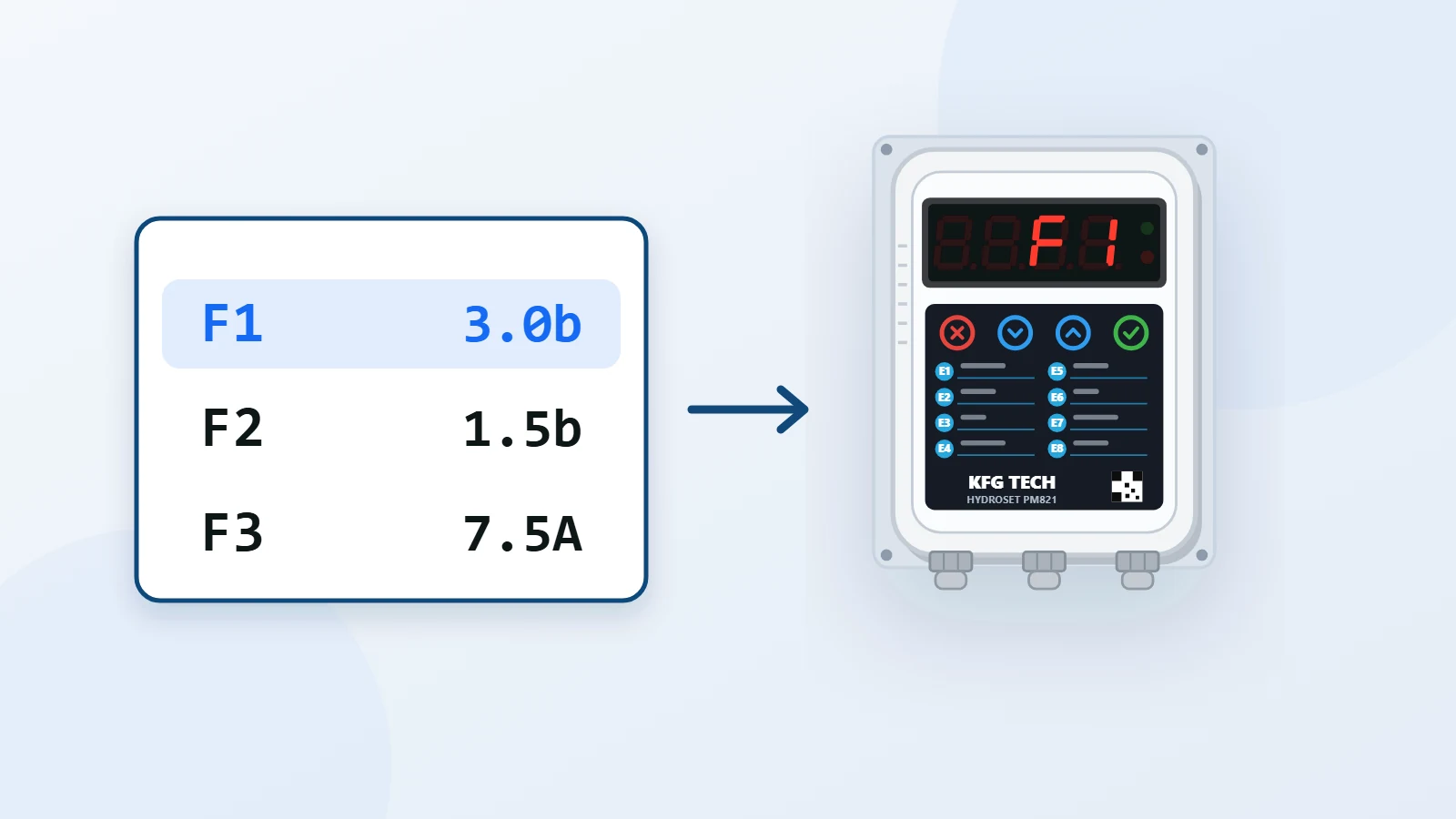
HYDROSET PM821 is set with fifteen parameters, F1 to F15. In most buildings only four of them, F1, F2, F3 and F4, need changing; the rest work correctly at their factory values. This guide starts with the keys and the display, covers setup in five steps, and then explains every parameter one by one: what it does, its factory value and when to change it.
The display and the keys
In normal operation the display shows the water pressure. A number ending in b is the pressure in bar, and a number ending in A is the pump current in amps.
| Display | Meaning | When you see it |
|---|---|---|
| 1.0b | Water pressure in bar | Normal operation |
| 1.0A | Pump current in amps | With the Down key, while the pump is running |
| E 3 | Fault code, flashing | When a fault has occurred and the pump is stopped |
While the pump is running, the Down key shows the pump current; when the pump stops, the display goes back to pressure.
| Key | Function |
|---|---|
| Confirm | Enter the settings, enter a parameter, store a value |
| Up | Go to the next parameter, increase the value, show the pressure |
| Down | Go to the previous parameter, decrease the value, show the pump current |
| Cancel | Leave without saving, leave the settings, clear a fault |
Entering the settings and saving
- Press the Confirm key to enter the settings.
- Use the Up and Down keys to go to the parameter you want.
- Press Confirm to enter the parameter, change the value with Up and Down, and store it with Confirm.
- Leave the settings with the Cancel key.
You can also make all of these settings with the pump controller setup app on an Android phone; it connects over Bluetooth and works in the pump room without internet.
Setting up HYDROSET in five steps
When the unit is powered up, it shows its name and spends about 30 seconds getting ready; the pump does not start during this time. Then:
- Set F1 and F2 with the formula in the next section.
- Leave one tap open so the pump keeps running. Read the pump current with the Down key and store that figure, plus at least 0.5 A, in F3.
- Keep the tap open, close the pump inlet valve and wait a moment. The current now shown is the dry-running current.
- Store that figure, plus at least 0.5 A, in F4, and open the inlet valve again.
- Leave the settings with the Cancel key. The unit is ready to work.
F2 must be lower than F1, and F4 lower than the pump's normal working current; otherwise the unit reads normal running as dry running.
Working out the right pressure (F1 and F2)
The right pressure depends on the building height: from where the pump is installed to the highest tap, in metres.
- F1 = (building height ÷ 10) + 2
- F2 = F1 − 1.5
Every 10 metres of height needs 1 bar of pressure, and the 2 is the pressure wanted on the top floor. For a 10-metre building, for example, F1 is 3 bar and F2 is 1.5 bar.
| Building height | Suggested F1 | Suggested F2 |
|---|---|---|
| 10 m (3 floors) | 3.0 bar | 1.5 bar |
| 15 m (5 floors) | 3.5 bar | 2.0 bar |
| 20 m (7 floors) | 4.0 bar | 2.5 bar |
| 30 m (10 floors) | 5.0 bar | 3.5 bar |
- The pump must be able to reach the F1 pressure, otherwise it never stops. A simple check: the pump head (on the nameplate, in metres) must be greater than "building height + 20 metres".
- Avoid more pressure than you need; high pressure damages the solenoid valves of washing machines and dishwashers and shortens the life of the fittings.
- If the pump is connected directly to the mains water pipe, the mains pressure adds to the pump pressure and a smaller pump is enough.
Every HYDROSET parameter in one table
| Parameter | Name | Range | Unit | Factory (8 A model) | Factory (16 A model) |
|---|---|---|---|---|---|
| F1 | Pump stop pressure | 0.1 to F13 | bar | 3.0 | 3.0 |
| F2 | Pump start pressure | 0.1 to F1 | bar | 1.5 | 1.5 |
| F3 | Maximum pump current | 1 to 8 or 16 | A | 7.5 | 10.0 |
| F4 | Minimum pump current (dry-run sensitivity) | 0 to F3 | A | 1.0 | 1.0 |
| F5 | Dry-run detection time | 0 to 600 | seconds | 20 | 20 |
| F6 | Retry interval | 0 to 600 | minutes | 20 | 20 |
| F7 | Start delay | 0 to 600 | seconds | 0 | 0 |
| F8 | Stop delay | 0 to 600 | seconds | 0 | 0 |
| F9 | Display brightness | 0 to 7 | — | 7 | 7 |
| F10 | Dry-run detection pressure | 0 to F1 | bar | 1.0 | 1.0 |
| F11 | Soft-start time | 0.1 to 600 | seconds | 0.2 | 0.2 |
| F12 | Soft-stop time | 0.1 to 600 | seconds | 0.2 | 0.2 |
| F13 | Maximum sensor pressure | 1 to 100 | bar | 20 | 20 |
| F14 | Pressure sensor calibration | 0 to 2000 | — | Unit-specific | Unit-specific |
| F15 | Pressure sensor offset adjustment | 0 to 1 | command | 1 | 1 |
The parameters fall into three groups: pressure control (F1, F2, F7, F8), pump protection (F3, F4, F5, F6, F10) and start-up and display (F9, F11, F12). F13 to F15 belong to the pressure sensor and are changed only when the sensor is replaced.
Pressure control: F1, F2, F7 and F8
F1 is the stop pressure and F2 the start pressure of the pump. The pump works between these two figures: it starts when the pressure falls to F2 and stops when it reaches F1, and between the two it keeps its current state. A gap of 1 to 1.5 bar between F1 and F2 is right.
F7, the start delay, is how long the pressure must stay below F2 before the pump starts, and F8, the stop delay, how long the pressure must stay above F1 before the pump stops. Both are in seconds, and 0 means no delay. If very short draws make the pump switch on and off again and again, a delay of a few seconds stops it. The other causes are covered in why a water pump keeps switching on and off.
Pump protection: F3, F4, F5, F6 and F10
F3, the maximum pump current, is the current limit. If the pump current stays above F3, the unit stops the pump and shows fault E1. Read the figure on the unit as in step 2 of the setup, or take it from the pump nameplate. The maximum value of F3 is eight amps on PM821-8 and sixteen amps on PM821-16.
F4, the minimum pump current, is what the market calls "controller sensitivity": the current the pump draws when it has no water. The unit uses this figure to detect dry running from the current. A value of 0 turns this detection off.
F10, the dry-run detection pressure, is the second way of detecting dry running, from the pressure: if the pump is running and the pressure stays below F10 for the F5 time, fault E4 is recorded. F10 must be lower than the pump's normal working pressure. A value of 0 turns this detection off.
F5, the dry-run detection time, is how long the dry-run condition must last before a fault is recorded. A short time makes detection faster but more sensitive. F6, the retry interval, is how long the unit waits after a dry-run fault before starting the pump again to see whether the water has come back.
The dry-run protection cycle works like this:
- The pump is running and its current falls below F4, or the pressure below F10.
- This lasts for F5 seconds.
- The pump stops and a dry-run fault (E3 or E4) is shown.
- The unit waits F6 minutes and starts the pump again.
- The cycle repeats until the water comes back; when it does, the fault clears by itself and the pump returns to normal operation.
More detail is in why pumps run dry and how to stop them burning out.
Soft start and the display: F11, F12 and F9
The unit does not start the pump all at once. F11, the soft-start time, is how long the pump power takes to rise from zero to full, and F12, the soft-stop time, how long it takes to fall to a complete stop. This prevents water hammer. The suggested value for both is 0.2 to 1 second.
F9, display brightness, runs from 0 to 7, with 7 the brightest. When you change it, the effect shows on the display at once.
The pressure sensor: F13, F14 and F15
- F13 is the maximum sensor pressure. The sensor supplied with the unit is 20 bar, and F13 is changed only when the sensor is replaced.
- F14, the sensor calibration factor, is calibrated separately for each unit at the factory and may differ from one unit to another. Write its value down and don't change it, except when replacing the sensor.
- F15 is the sensor offset adjustment command. A value of 1 starts the adjustment, and once it is done the value returns to 0 by itself.
There is a green light on the back of the sensor; when it is on, the sensor is healthy.
Replacing the pressure sensor
If the sensor is damaged, use a standard sensor with a 0.5 to 4.5 V output and follow these steps in exactly this order:
- Enter the new sensor's maximum pressure in F13.
- Set the F14 factor back to 150.
- Remove the sensor from the pipe and make sure there is no pressure on it.
- Enter F15 and set it to 1.
- Leave the settings. The unit adjusts the sensor and stores the value.
If something goes wrong, repeat the steps from the beginning.
Settings for special cases
With and without a pressure vessel: The unit works either way. If you have a pressure vessel, set its air pre-charge about 0.2 bar below F2; how to do it is in pressure vessel pre-charge.
Three-phase pump and contactor: The unit's output drives the contactor coil, and the pump current does not pass through the unit. So set F4 to 0 so that fault E3 does not appear for no reason, and leave dry-run detection to F10. In this setup the overcurrent protection (F3) does not see the pump current either. How to connect the contactor is in pump controller wiring.
Direct connection to the mains pipe: The mains pressure adds to the pump pressure; set F1 and F2 to the pressure the building actually needs, no more.
Common setting mistakes
| Mistake | Result | The right way |
|---|---|---|
| F4 above the pump's normal working current | The unit reads normal running as dry running and shows E3 for no reason | Measure F4 again with steps 3 and 4 of the setup |
| F10 above the pump's normal working pressure | Fault E4 although the water has not been cut off | Set F10 below the normal working pressure |
| F1 beyond what the pump can deliver | The pump never reaches F1 and never stops | Work out F1 with the formula; the pump head must be greater than building height + 20 metres |
| Small gap between F1 and F2 | The pump keeps switching on and off | Keep the gap at 1 to 1.5 bar; add F7 and F8 if needed |
| F3 below the pump's actual current | Fault E1 during normal running | Read the pump current and store it, plus 0.5 A, in F3 |
| Changing F14 | The displayed pressure becomes wrong | Write down F14 on day one and change it only when replacing the sensor |
If the unit shows a fault code, the cause and fix for each code are in pump controller fault codes. To choose the right model for a building, see the pump controller selection calculator.
The full manual, with every parameter's range, is in the HYDROSET PM821 user manual.