Wiring a water pump controller: the input and output terminals, the connection order, the miniature circuit breaker, contactor mode and testing after wiring. Based on the HYDROSET PM821 manual.
Wiring a pump controller isn't complicated, but the order and quality of the connections matter. Most faults seen after installation come from a loose terminal or wires connected the wrong way round. This guide explains the wiring of the HYDROSET PM821 according to its manual.
Before anything else, switch off the circuit at the miniature circuit breaker. If you are not familiar with electrical work, leave the wiring to an electrician.
Supply to the unit
- The unit's operating voltage is 180 to 240 V single-phase.
- The unit's output voltage equals its input voltage; the pump gets the same supply that reaches the unit.
- The unit itself uses less than 5 watts.
Terminals
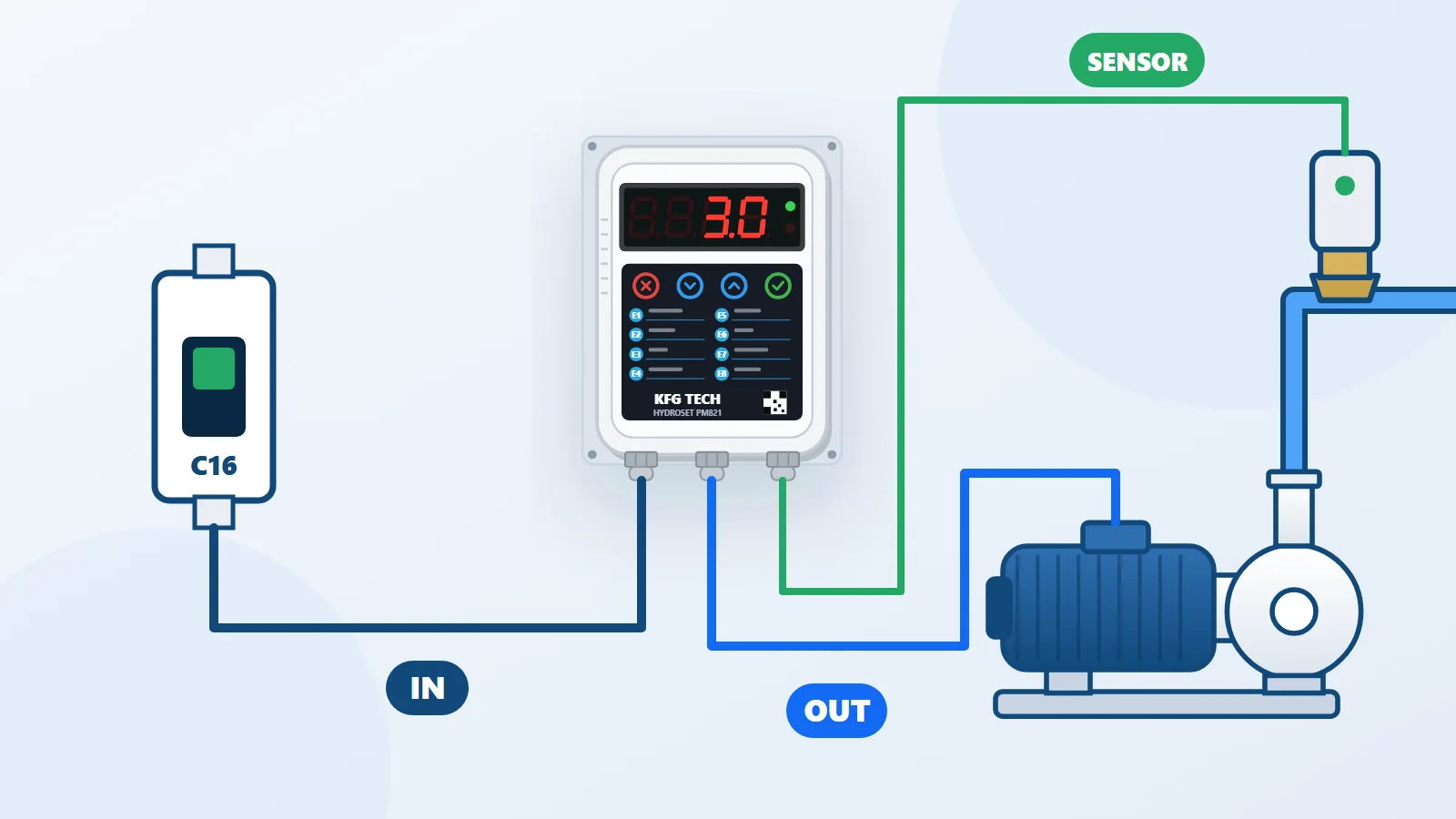
The unit has separate terminals for input and output, and each wire carries a label showing whether it goes to the pump or to the mains.
| From | To |
|---|---|
| Panel supply, after the miniature circuit breaker | Unit input terminal |
| Unit output terminal | Pump |
| Pressure sensor (fixed cable) | Unit |
Connection order
- Read the labels beside the wires.
- Connect the output wire to the pump terminal.
- Connect the input wire to the mains last.
Replacing a mechanical automatic switch
In old wiring, the pump's power passed through the mechanical pressure switch. When the pump controller takes its place, the mains goes to the unit's input and the pump takes its power from the unit's output. The pressure sensor screws in where the pressure switch sat on the five-way manifold, after the check valve. No change to the pipework is needed. Keep the pump's earth wire connected according to the building wiring.
Miniature circuit breaker
Choose the miniature circuit breaker to suit the pump's power, not smaller. At start-up the motor draws more current than its normal running current, and a small breaker trips at that very moment. The table of the right breaker for each model is in the pump controller selection guide.
Contactor mode
If the unit's output is connected to a contactor, the contactor switches the pump on and off and the pump current does not pass through the unit. In that case the unit cannot see the pump current, so:
- Set F4 to 0 so that E3 is ignored.
- Detect dry running by pressure, that is, rely on F10.
Connection quality
Push the wires fully into the terminal and tighten the terminal screw. A loose connection has three consequences: a hot terminal, a voltage drop and faults on the display. A loose output terminal is one of the common causes of fault E2; the unit sees no current from the pump and stops it.
Sensor cable
The sensor cable is fixed to the sensor. Before tightening, turn the sensor backwards a few turns and then screw it in, so the cable doesn't twist. Route the cable where it won't be underfoot or next to a sharp edge; a cut cable causes fault E6.
Testing after wiring
- Switch the power on. The unit shows its name and prepares for about 30 seconds.
- The green light on the back of the sensor should be on.
- Read the line pressure on the display.
- Open a tap; when the pressure falls below F2, the pump should start.
- Read the pump current with the Down key and compare it with the pump nameplate.
After wiring, set parameters F1 to F4 as described in Setting a water pump controller. Fitting the sensor and the pipework are covered in the installation guide.
The difference between single-cable and dual-cable models is explained in Single-cable or dual-cable pump controller.